
PSD Calculation
PSD calculation process
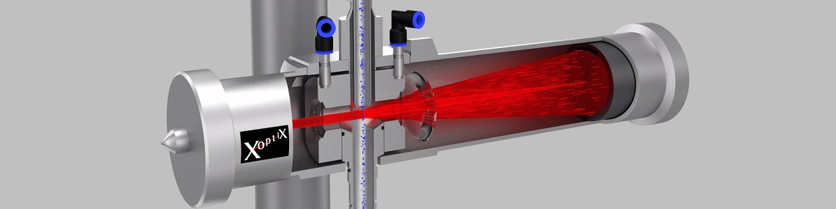
Laser diffraction instruments measure scattered light intensity at multiple detector positions. In this example, 32 detectors collect light at different scattering angles, from small angles to wider angles. Each detector receives a signal that corresponds to how much light was scattered in that angular range.
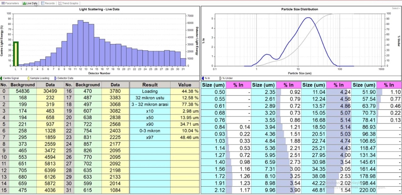
The measured detector signals are then corrected for background, laser intensity, optical alignment, and detector sensitivity. This produces a clean set of 32 intensity values that represent the scattering pattern of the particle cloud passing through the laser beam.
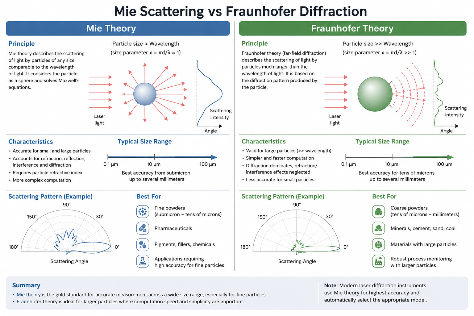
The key idea is that different particle sizes create different scattering patterns. Large particles mainly scatter light at small angles, while fine particles scatter more light at wider angles. The instrument compares the measured 32-detector pattern with theoretical scattering patterns calculated using Mie theory or Fraunhofer approximation.
The software then solves an inverse calculation: it finds the particle size distribution that would produce the measured detector intensities. In simple terms, it tests many possible particle size fractions and determines the combination that best matches the real scattering signal.
The final result is converted into a PSD curve, usually showing volume percentage versus particle size. From this curve, values such as D10, D50, D90, D98, or percentage below a target size can be calculated and used for process monitoring, alarms, or automatic control.
Detector channel 1 is designed differently from the other detectors in the array. Instead of a standard detector segment, channel 1 consists of a small hole located at the centre of the detector array, with a photodiode positioned directly behind it. The direct laser beam passes through this opening and reaches the photodiode, allowing the system to continuously measure the transmitted laser intensity.
As particle concentration increases inside the measurement zone, more light is scattered away from the direct beam, reducing the amount of light reaching the photodiode behind channel 1. This signal is used to calculate laser attenuation and determine sample loading conditions in real time. By monitoring the transmitted beam intensity, the system ensures that the particle concentration remains within the optimal operating range for accurate and reproducible PSD measurements.
In production conditions, the attenuation signal from channel 1 also provides valuable information about the presence and stability of the sample flow. If no material is present, the transmitted laser intensity remains too high, immediately indicating loss of sample or interruption of the sampling system. Sudden fluctuations in attenuation can also reveal unstable feeding, blocked lines, inconsistent dispersion, or incorrect sampling conditions. In this way, channel 1 acts not only as a sample loading monitor, but also as a real-time diagnostic tool for verifying correct operation of the entire sampling and measurement system during continuous industrial operation.
In industrial process control, however, the main objective is often not to know the exact particle size at a single moment, but to continuously observe how the process behaves over time. Real value comes from stable real-time trends that allow operators to immediately detect process changes, disturbances, or abnormal conditions. A continuously updated PSD trend provides far more operational insight than occasional isolated laboratory measurements.
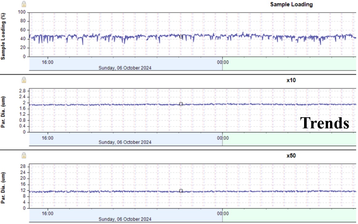
By plotting particle size trends continuously, operators can understand how the grinding circuit responds to changes in feed material, separator settings, mill conditions, or process disturbances. The trend itself becomes the key process signal used for optimisation, alarms, troubleshooting, and automatic control. In many industrial applications, stable and reproducible trending is more important than absolute laboratory-level accuracy, because process optimisation depends primarily on observing relative process changes in real time.